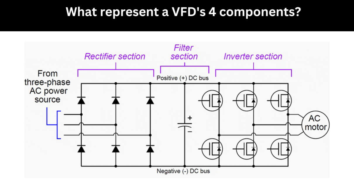
A variable frequency drive (VFD) typically includes these four elements:
1. Rectifier:
A VFD’s initial part is a rectifier. This device converts the incoming AC electricity (often from the utility grid) into DC power. Direct current (DC), which is then used by the other components of the VFD, is created by the rectifier by converting alternating current (AC) into AC.
- AC-to-DC Conversion: The utility grid-sourced AC power supply is converted into DC power by the rectifier circuitry. It makes it possible for the variable frequency drive (VFD) to work with a DC power source, which is necessary for the drive’s later stages.
- Voltage Rectification: The rectifier converts the alternating voltage’s waveform into the unidirectional voltage’s waveform. Rectifying the negative half-cycles of the AC waveform results in a pulsating DC voltage waveform.
- Current Control: The amount of current that is drawn from the AC power source is controlled by the rectifier. It regulates the current flow based on the requirements of the load and the control signals obtained from the VFD’s control circuit.
2. DC Bus:
The DC Bus serves as a middle storage device for the DC power generated by the rectifier. Along with reducing DC voltage peaks and valleys, it also serves as a reservoir to provide consistent DC voltage to the following step.
- Function: The rectifier converts the incoming AC power into DC power, which is then stored in the DC Bus as a buffer or reservoir. It helps to maintain a constant and stable voltage level and lessens any DC voltage fluctuations.
- Capacitor Bank: The DC Bus is a capacitor bank that is typically connected in parallel across the DC power lines. The capacitors act as energy storage units and aid in the stability of the DC voltage level by accumulating or releasing charge as needed.
- Energy Storage: The DC Bus serves as an energy storage system inside the VFD. It provides a source of energy that can be used when load demand changes quickly, the motor needs to accelerate or decelerate, or when the VFD requires more power.
- Voltage Stabilization: Inverter DC voltage is managed with the help of the DC Bus. It ensures that the voltage remains within the predetermined range, which is necessary for the VFD and linked motor to operate properly.
Check :- Rockwell Automation PowerFlex 4M AC Drive
3. Inverter:
The inverter is a crucial part of the VFD because it converts DC power from the DC Bus back into AC power with adjustable frequency and voltage. Insulated Gate Bipolar Transistors (IGBTs) are used in power electronics to produce the desired output voltage and frequency based on the control signals the VFD’s control circuit sends out.
- Function: The primary function of the inverter is to control the output voltage and frequency to the connected motor so that it can operate at different speeds.
- Power Conversion: The inverter uses power electronic components, most frequently Insulated Gate Bipolar Transistors (IGBTs), to convert the DC power from the DC Bus into a three-phase AC output. By altering the components’ switching patterns, the inverter can create an AC waveform with variable frequency and voltage.
- Voltage and Frequency Control: The inverter alters the magnitude and frequency of the output voltage to control the motor’s speed and torque. Because they enable precise control over the average voltage that the motor perceives, pulse width modulation (PWM) techniques are frequently used to modify the output voltage.
4. Control Circuit:
The VFD’s operation is supervised and managed by the control circuit. Microprocessors, numerous input/output interfaces, and control algorithms make up this system. In order to control the motor’s speed and torque, the control circuit modifies the inverter’s output voltage and frequency in accordance with signals or setpoints. To monitor and protect the motor as well, it includes safety precautions and defect detection systems.
- Motor Control: The control circuit receives control signals from the operator or an external control system and converts them into the appropriate commands for the VFD. It determines the necessary speed and torque setpoints for the motor and modifies the inverter’s output voltage and frequency accordingly to achieve the desired motor performance.
- Control Algorithms: The control circuit incorporates sophisticated control software and algorithms to implement multiple motor control schemes. These algorithms allow for smooth and precise regulation of the motor’s speed, torque, and acceleration based on inputs from the operator or the control system.
- Monitoring and Protection: The control circuit routinely monitors a number of parameters, including voltage, current, temperature, and fault conditions, to protect the motor and the VFD. It has protection features like overcurrent protection, overvoltage protection, undervoltage protection, thermal overload protection, and short circuit protection to stop motor damage and guarantee safe operation.
- User Interface: The control circuit’s user interface, which can be a control panel or graphical display, allows operators to configure and monitor the VFD’s parameters. It allows the user to choose the required motor speed, examine the motor’s condition, modify the control parameters, and obtain diagnostic information.
Together, these four parts convert the incoming AC power into controlled outputs with varying frequencies and voltages that drive and control the attached motor.
Asteam Techno Solutions Pvt. Ltd. is a leading and preferred solution provider for all kind of Industrial Automation requirements in the field of Process and Power Automation. Established in 2017, Asteam Techno Solutions is an ISO 9001: 2015 certified company, having its Design, Manufacturing & Repair facility located in Surat, Gujarat, India and provides total integration under one roof.